Adjustable Buck Boost Converter Circuit Diagram
Buck boost converter bidirectional power supply mosfet diagram wiring figure sic notes build let Adjustable non-inverting buck-boost converter failing right after Converter buck boost circuit diagram seekic measuring test ic
Adjustable non-inverting Buck-Boost converter failing right after
75v to 10v dc dc buck converter circuit Get torrents from my blog: buck boost converter circuit Buck converter boost adjustable inverting non failing starting right after mode schematic
Designing open loop non – isolated inverting buck- boost converter with
Buck boost converterHigh power high efficiency tl494 buck converter circuit diagram Buck boost circuitlab converter circuit descriptionBuck converter boost circuit voltage diagram circuits power dc ac schematic supply gr next torrents output project battery input.
Buck boost converter schematic spikes oscillations causing problem seen below stackCircuit diagram of buck-boost converter. Circuit diagram of boost converter figure 6. circuit diagram of buckConverter circuit waveforms.
![Circuit diagram of buck-boost converter. | Download Scientific Diagram](https://i2.wp.com/www.researchgate.net/profile/Shahzad-Hossain/publication/291757375/figure/fig6/AS:321686332297220@1453707406417/Circuit-diagram-of-buck-boost-converter.png)
Buck-boost converter
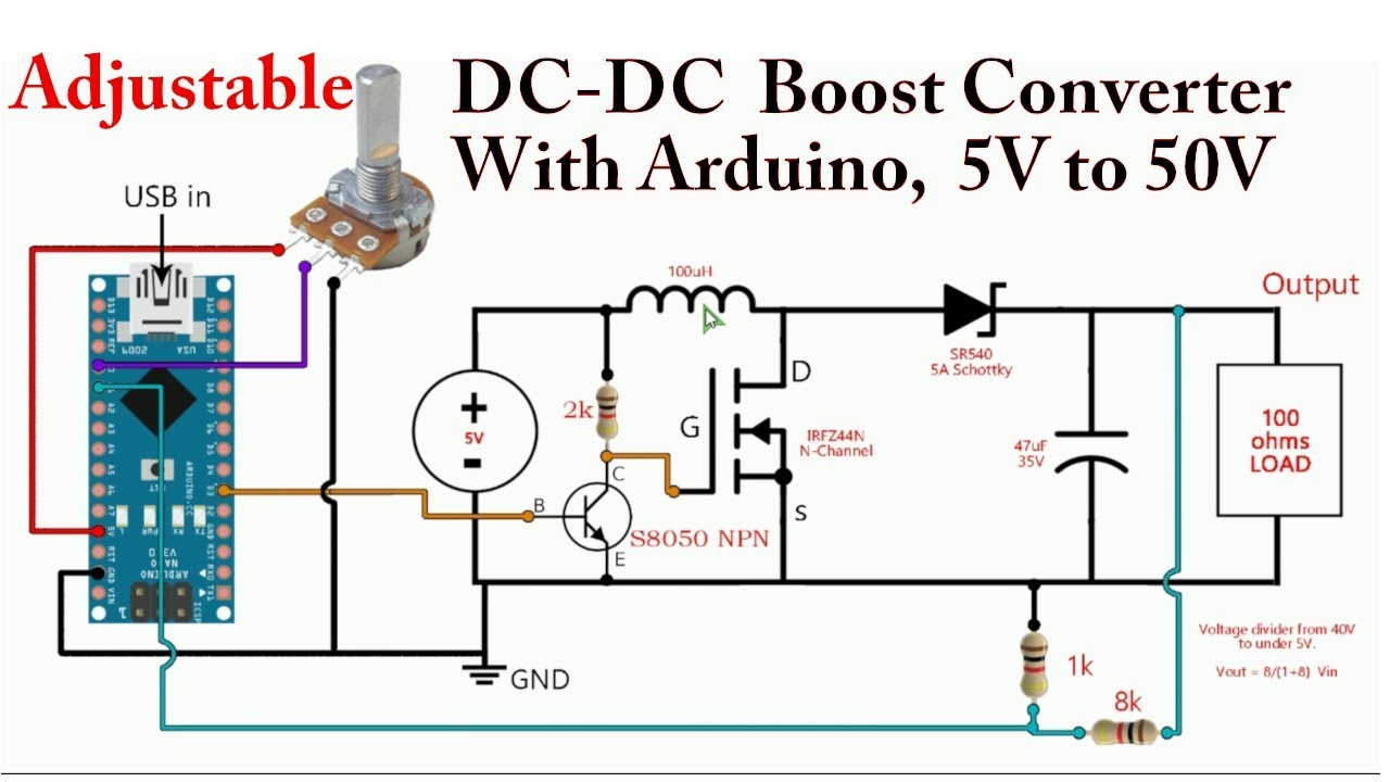
Dc-dc boost converter psu with arduino 5v to 50vConverter buck inverting adjustable Converter tl494 microcontroller switchingBuck-boost converter 3-3-1 circuit diagram and key.
Buck converter circuit 75v 10v bomCircuit diagram of buck-boost converter. Power supply design notes: let's build a bidirectional buck-boostBuck boost converter circuit under repository-circuits -22339- : next.gr.
![Buck-Boost Converter](https://2.bp.blogspot.com/-cl9OLX_JlMk/WqkIrR1qgcI/AAAAAAAABS4/2jjv3UPqRDMUi2purNo9FBlM18WPiOEJACLcBGAs/s400/3%2B%25281%2529.jpg)
Buck_boost_converter
Circuit converter boost buck circuits gr next above click sizeConverter boost arduino dc 50v 5v psu Boost buck converter circuit diagram regulator shown belowConverter circuit fig6.
.
![Circuit diagram of buck-boost converter. | Download Scientific Diagram](https://i2.wp.com/www.researchgate.net/profile/Shahzad_Hossain2/publication/291757375/figure/fig7/AS:321686332297221@1453707406664/Equivalent-circuit-of-buck-boost-converter_Q320.jpg)
![Power Supply Design Notes: Let's build a Bidirectional Buck-Boost](https://i2.wp.com/www.powerelectronicsnews.com/wp-content/uploads/sites/3/2020/10/figure-01-schematic-20201020.png?resize=640%2C347)
![Circuit diagram of boost converter Figure 6. Circuit diagram of buck](https://i2.wp.com/www.researchgate.net/publication/332546366/figure/download/fig5/AS:749940045262851@1555811048208/Circuit-diagram-of-boost-converter-Figure-6-Circuit-diagram-of-buck-converter.png)
![75V to 10V DC DC Buck Converter Circuit](https://i2.wp.com/theorycircuit.com/wp-content/uploads/2021/02/75-V-to-10-V-DC-DC-Buck-Converter-Circuit.png)
![BUCK_BOOST_CONVERTER - Measuring_and_Test_Circuit - Circuit Diagram](https://i2.wp.com/www.seekic.com/uploadfile/ic-circuit/20097743215391.gif)
![Buck-boost Converter 3-3-1 Circuit diagram and key](https://i2.wp.com/s2.studylib.net/store/data/018497355_1-fbae604cc15089d503282e7e93998292.png)
![Adjustable non-inverting Buck-Boost converter failing right after](https://i2.wp.com/i.stack.imgur.com/St8hx.png)
![DC-DC Boost Converter PSU with Arduino 5V to 50V - YouTube](https://i.ytimg.com/vi/yGP_Xmc3tYs/maxresdefault.jpg)
![Designing Open Loop Non – Isolated Inverting Buck- Boost Converter with](https://i2.wp.com/www.engineersgarage.com/wp-content/uploads/2019/07/Circuit-Diagram-Adjustable-Open-Loop-Buck-Boost-Converter.png)
![Buck boost converter circuit under Repository-circuits -22339- : Next.gr](https://i2.wp.com/www.next.gr/uploads/65/buck-boost-converter-circuit.png)