Pwm 4 Pin Diagram
Pwm voltage module circuit diagram v1 codrey Pwm ( for motor) Diy projects
PWM ( for motor) | Electronic schematics, Electronic circuit projects
What are the standard pwm output signals that a microcontroller should Pwm wiring diagram Pwm wiring diagram
Pwm signals microcontroller generate
Pwm arduino componentPwm arduino does work regarding points clear couple let Pwm control fans using mosfet controlling mobo pump water techpowerup forums framed items connectors bluePwm 4-pin to 3-pin conversion, electrical advice wanted!.
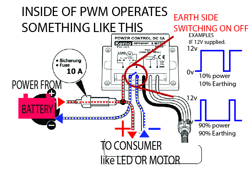
Mechanic page: how to wiring pwm module and why?Circuit design Pwm circuit dc drivers power electric layout picotech motors some gifPwm controlling mobo pump fans control using water techpowerup forums.

Secrets of arduino pwm
Pwm diyPwm wiring diagram Potentiometer controlled properly behaving schematics forgive newbieControlling 3-pin fans (or water pump) using 4-pin pwm control from.
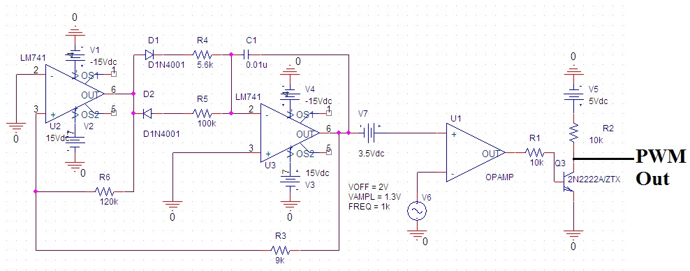
Controlling 3-pin fans (or water pump) using 4-pin pwm control fromPwm to voltage module (v1) Pwm fan negative positive 4pin computer fans rgb pinout pc wiring pins cable power riing 12v connect dc signal corsairPwm circuit schematic modulation pulse width figure.

Pwm noise emi grounding modulation controller shielded signals actuator outputs instrumentation reduce reducing prevent neuwied yoga logic
To the rails: april 2011Pwm wiring iq Public circuits tagged "pwm"Pwm october larger click.
Some power pwm drivers for electric dc motorsSaros electronics: october 2011 Hho pwm diagram circuit schematic nrg alt pulse width modulation v2 layout plans parts list board electrolysis current 150a innenPwm public switched source circuitlab circuits tagged.
Pwm module wire mechanic understand four easy little has
Pwm circuit modulation width speed electronic electronicsPwm led ciclo dimming Pwm module why wiring mechanic confusing connect need theyPwm v2.1 plans, parts list, board layout and schematic.
Mechanic page: how to wiring pwm module and why? .


